
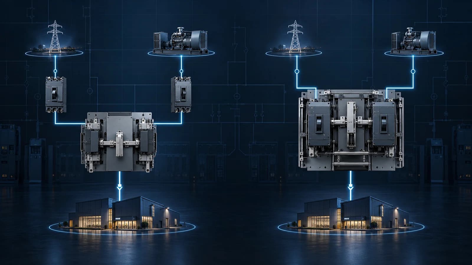
Short answer: under IEC transfer-switch terminology, a Class PC transfer switching device can make and withstand short-circuit current but is not intended to break that current. It relies on coordinated upstream overcurrent protection. A Class CB device can make, withstand and break short-circuit current and is provided with overcurrent releases. Neither class is universally better. The correct choice depends on the protection architecture, prospective fault current, continuity requirements, maintenance strategy, available space and project specification.
This is a more useful distinction than saying “PC is a switch” and “CB is two breakers.” Real products must be evaluated as complete transfer switching equipment, with their stated ratings, utilization category, interlocking, controller functions and test documentation.
For an overseas buyer or panel builder, the practical question is not only “PC or CB?” It is: what is expected to detect and clear an overcurrent or short circuit at the ATS location, and has the complete combination been selected and documented correctly?
What do PC Class and CB Class mean?
IEC 60947-6-1 covers transfer switching equipment used to transfer a load between power sources. The current edition published by IEC is IEC 60947-6-1:2026. The standard's scope includes manually operated, remotely operated and automatic transfer switching equipment, as well as several specific arrangements.
ABB's selection guide summarizes the short-circuit classifications as follows:
- Class PC: transfer switching equipment capable of making and withstanding short-circuit currents, but not intended to break them.
- Class CB: transfer switching equipment capable of making, withstanding and breaking short-circuit currents, and provided with overcurrent releases.
Those definitions concern short-circuit function. They do not tell you the current rating, pole count, neutral arrangement, transition method, controller voltage, mechanical endurance or communication capability. All of those still require model-level confirmation.
How does a PC Class ATS protect the circuit?
A PC Class ATS performs the source-transfer function while a separate upstream protective device—typically a circuit breaker or fuse—clears overcurrent and short-circuit conditions. The designer coordinates the ATS's short-circuit capability with that protective device and the available fault current at the installation point.
This separation can be advantageous where the protection scheme is already defined in the switchboard. It can also support a compact transfer mechanism. However, “protection is upstream” must not become “protection is somebody else's problem.” The ATS supplier and panel designer need sufficient information to verify the selected combination.
At minimum, provide:
- prospective short-circuit current at the ATS location;
- upstream breaker or fuse manufacturer, type and rating where known;
- system voltage and frequency;
- ATS rated operational current and utilization category;
- number of poles and neutral arrangement;
- expected load type and starting/inrush behavior;
- required conditional short-circuit or withstand rating evidence;
- destination-market standard and project specification.
If the project team does not yet know the available fault current, mark the item as unresolved. A factory cannot responsibly convert a blank fault-current field into a verified coordination claim.
How does a CB Class ATS differ?
A Class CB transfer switch incorporates devices with overcurrent releases and is intended to break short-circuit current. In practical equipment, this often means circuit-breaker-based switching devices with electrical and mechanical interlocking and an automatic controller.
This can consolidate switching and protective functions, but it introduces design questions of its own:
- What type of breaker and trip unit is used?
- Are trip settings fixed or adjustable?
- How are the two source devices interlocked?
- What happens after an overcurrent trip?
- Can the controller distinguish a source failure from a protective trip?
- Does the system lock out automatic transfer after a trip?
- How is selectivity coordinated with upstream and downstream protective devices?
- What manual operation and isolation procedure applies?
The answer depends on the offered equipment. “CB Class” is not a substitute for the actual schematic, settings and operating sequence.
PC Class vs CB Class ATS comparison
| Decision point | PC Class ATS | CB Class ATS |
|---|---|---|
| Short-circuit role | Makes and withstands; not intended to break short-circuit current | Makes, withstands and is intended to break short-circuit current |
| Overcurrent release in the transfer equipment | No; depends on coordinated external protection | Yes; provided as part of the CB equipment |
| Protection architecture | ATS plus upstream breaker/fuse | Transfer and overcurrent functions combined in the CB equipment, with wider system coordination still required |
| Typical buyer task | Verify conditional/withstand capability with the stated protective device | Verify breaking capacity, trip-unit behavior, settings and system selectivity |
| Space and mechanism | Can support a compact purpose-built transfer mechanism; model-specific | Often larger or more complex; model-specific |
| After-fault behavior | Upstream protective device clears the fault; restoration follows the system procedure | Offered device may trip and lock out or require reset; verify the exact sequence |
| Documentation focus | ATS ratings plus the permitted/proven protection combination | ATS/CB ratings, releases, settings, breaking capacity and interlocking |
| Common purchasing mistake | Checking only rated current and ignoring fault-current coordination | Assuming integrated breakers eliminate the need for coordination studies |
Is PC Class less safe than CB Class?
No—not when it is correctly selected, coordinated and installed. The two classes implement different protection architectures. A PC Class ATS is not supposed to interrupt a short circuit; the appropriate upstream device must do that job. A CB Class ATS includes overcurrent releases and is intended to break the fault under its defined ratings.
Safety depends on the complete system: device ratings, available fault current, protection settings, conductor sizing, enclosure design, installation quality and maintenance. A wrongly coordinated CB solution can be unsafe, just as an uncoordinated PC solution can be unsafe.
Avoid sales language that describes one class as “advanced” and the other as “basic.” Explain the operating responsibility of each device and show the evidence for the offered combination.
Seven questions that should drive the selection
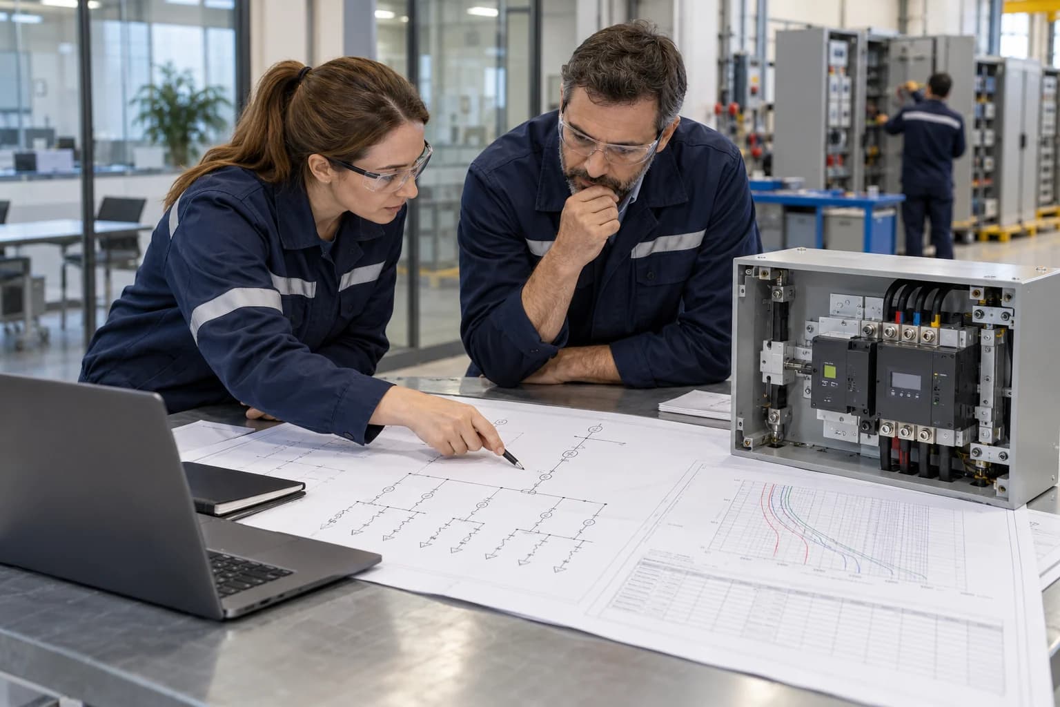
1. What does the project specification require?
Start with the one-line diagram, equipment schedule and written specification. If the document explicitly calls for Class PC or Class CB, quote that basis and identify any exception. Do not silently substitute because another product is cheaper or readily available.
2. What is the prospective fault current at the ATS?
This value is essential for checking the equipment's short-circuit capability. It is not the same as load current. If unavailable, the system designer may need a fault-current study or a documented design assumption.
3. Which device will clear the fault?
For Class PC, identify the upstream breaker or fuse and verify the permitted coordination. For Class CB, identify the overcurrent release and required breaking capability. In both cases, study selectivity with the rest of the system.
4. How important is continuity after a downstream fault?
The transfer sequence after a protective operation must be intentional. An ATS must not transfer a load simply to re-energize a persistent fault from the alternate source. Confirm trip logic, lockout behavior, alarms and reset procedures.
5. What load is being transferred?
Motors, transformers, LED drivers, UPS inputs and mixed commercial loads can have inrush or transient behavior that differs from steady-state current. Confirm the appropriate utilization category and model ratings. Do not select only from a thermal load estimate.
6. What panel and maintenance constraints apply?
Consider mounting, terminal access, cable direction, required clearance, manual operating access and replacement strategy. A technically valid device that cannot be wired, inspected or operated safely in the enclosure is not a complete solution.
7. What evidence must accompany the quotation?
Agree on the required datasheet, dimensional drawing, wiring diagram, instruction manual, declaration or certificate, test report, material list and settings record. The document scope must match the exact model and ratings—not just the product family name.
Understanding ratings without mixing them up
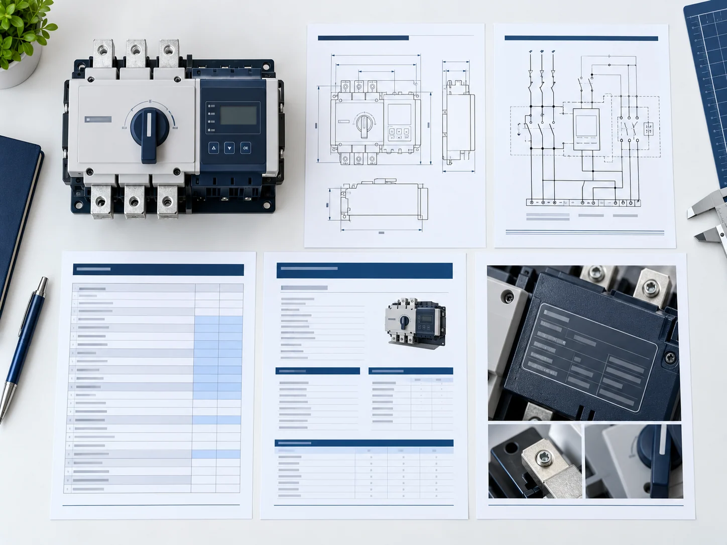
Procurement errors often occur because several different ratings are reduced to a single “kA” line. Keep the following concepts separate and use the terminology in the product's applicable documentation:
- Rated operational current: the continuous/load current for the specified conditions.
- Making capacity: the ability to close onto a current under stated conditions.
- Withstand capability: the ability to carry a fault current for a defined time or test condition without unacceptable damage.
- Breaking capacity: the ability to interrupt the fault current. This is central to Class CB equipment.
- Conditional short-circuit capability: performance when protected by a specified upstream protective device.
- Utilization category: the intended switching duty and load conditions under the relevant standard.
Do not copy a value from one model size, pole configuration or voltage and apply it to the whole family. Ask for the table, certificate or test evidence that covers the exact order code.
IEC 60947-6-1:2026: what buyers should know
IEC lists the 2026 publication as the fourth edition of IEC 60947-6-1. It replaced the 2021 edition and clarifies scope while adding specific annexes for bypass/isolation TSE, closed-transition ATSE, stand-alone ATS controllers and TSE for electric-driven fire-pump control equipment.
That does not mean every project immediately requires a 2026 document or that older installed equipment becomes invalid. Contracts, national adoption and certification schemes can reference different editions. It does mean buyers should stop writing “IEC 60947-6-1 compliant” as an undated slogan.
For each order, ask:
- Which edition is stated on the offered document?
- Which model numbers and ratings are in scope?
- Is the evidence a declaration, certificate, test report or datasheet?
- Who issued it and can its scope be verified?
- Does the destination market require an additional national standard, mark or approval?
An IEC logo or generic standard reference on a sales image is not sufficient technical evidence.
Factory testing and shipment inspection for PC or CB equipment
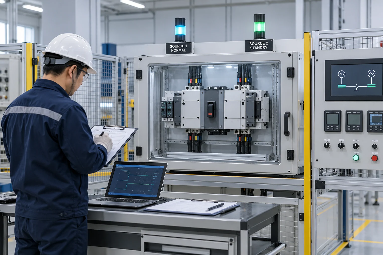
Factory testing should verify the product that was ordered, not recreate the entire site protection study. The test plan varies by device and project, but a buyer can structure the review around five evidence groups.
Product identity
Confirm model, frame/current, voltage, frequency, poles, class, controller version and accessories against the purchase order and approved datasheet. For OEM products, the private label must retain correct technical identification and required markings.
Mechanical operation and interlocking
Verify normal and alternate positions, manual operation under safe isolated conditions, mechanical interlock and freedom from binding. A transfer mechanism must not allow the two sources to be connected in an unintended manner.
Control and transfer sequence
Use the model-specific procedure to check source sensing, transfer, retransfer, delays, indication, generator-start contacts and automatic/manual mode. Record the agreed settings. Do not assume factory defaults match the project.
Protection-related checks
For a PC solution, verify the specified upstream protection reference and related short-circuit documentation. For a CB solution, verify breaker identity, release type, settings range, trip indication and post-trip behavior. The site team still must confirm installed protection settings and coordination.
Final inspection and documents
Inspect terminal condition, labels, accessories, barriers, packaging and quantities. Confirm that the wiring diagram, manual and test record belong to the shipped model revision. ABB's installation guidance emphasizes cable correctness, matching phase rotation, engine-start and control wiring, timer settings, lug torque, barriers and documentation before energization.
Installation preparation: turn the selected class into a working system
Before installation, the panel builder should reconcile the selected ATS with the protection study and approved drawings. Check enclosure space, heat dissipation, conductor routing, terminal capacity, protective-device location, neutral arrangement and safe manual access.
Before energization, qualified personnel should:
- verify both sources are correctly isolated during installation work;
- inspect for shipping damage and debris;
- confirm source/load cable identification and phase rotation;
- apply specified torque values;
- check control wiring, generator-start circuit and auxiliary I/O;
- load the approved controller and protection settings;
- reinstall barriers and covers;
- complete the manufacturer's commissioning procedure;
- record final settings and test results for handover.
A successful factory test cannot correct reversed phase rotation, wrong field wiring or unapproved settings at site. Factory acceptance and site acceptance serve different purposes.
How LSP's current range fits this comparison
LSP's current product data identifies representative L2H and M2R models as PC Class. That means the product discussion must include the upstream protective-device and fault-current context. It should never be represented as an integrated overcurrent-breaking solution unless the exact product documentation says so.
- L2H Series: representative 40A/63A, 2P/4P, with 110 V and 220 V control versions.
- M2R Series: representative 40A/63A/100A, 2P/3P/4P, with 110 V and 220 V control versions.
The L2S family should be described according to its current model-specific documents; do not infer a class only from appearance or mounting format.
For a quotation, send the current, voltage, phase, poles, control voltage, available fault current, upstream protection, load type, panel dimensions and required documentation. If the project requires Class CB, state it before model selection so the supplier can confirm whether the range is suitable rather than forcing a mismatch.
FAQ
What does PC Class mean on an ATS?
It means the transfer switching equipment is capable of making and withstanding short-circuit current under its defined ratings but is not intended to break that current. A coordinated upstream protective device must clear the fault.
What does CB Class mean on an ATS?
It means the transfer switching equipment can make, withstand and is intended to break short-circuit current, and it is provided with overcurrent releases. Verify the exact breaking capability, releases, settings and operating sequence.
Is a PC Class ATS suitable for a generator system?
It can be, provided the complete system—including upstream protection, fault-current level, utilization category, grounding and transfer sequence—is correctly designed. Generator use alone does not decide the class.
Does CB Class remove the need for upstream breakers?
Not necessarily. The complete power system still requires protection, isolation and coordination. The designer must establish the role and settings of every protective device.
Is the ATS ampere rating enough for selection?
No. Also confirm voltage, frequency, load type, poles, neutral, control voltage, utilization category, fault-current level, protection architecture, transfer method, panel conditions and applicable standard.
Which IEC 60947-6-1 edition is current?
IEC published IEC 60947-6-1:2026 as the fourth edition on 2 April 2026. The applicable edition for a project depends on contract requirements, certification scope and national adoption.
What should appear in an ATS quotation?
The quotation should identify the exact model, current, voltage, frequency, poles, class, control supply, main functions, accessories, required documents, quantity, packaging basis and any unresolved technical points.
Conclusion
PC Class and CB Class describe different short-circuit roles. PC equipment performs transfer while coordinated external protection clears faults. CB equipment combines transfer with overcurrent releases and fault-breaking capability. Both still require a complete engineering review.
The buyer's best protection against a wrong order is a clear one-line diagram, a known fault-current basis, named upstream protection, a defined load and a model-specific document package. If any of those are unknown, keep them visible as open technical actions rather than hiding them behind a generic “IEC ATS” description.
Final CTA: Request a Product and Protection Review
Send LSP your one-line diagram, load current, voltage, poles, available fault current, upstream protective device, control requirements, panel space and destination market. We will compare the requirement with the current ATS families and identify the model documents needed before sample approval.
Technical references
- IEC, IEC 60947-6-1:2026 publication page: https://webstore.iec.ch/en/publication/90494
- ABB, “How to select an automatic transfer switch class”: https://library.e.abb.com/public/a0a6a4a06b204e7bbf5988e6d35ee364/ATS%20white%20paper_1SCC303022C0201_20-09.pdf
- Schneider Electric, “What is a Transfer Switch?”: https://www.se.com/us/en/work/featured-articles/what-is-a-transfer-switch/
- ABB Zenith transfer switch manual, final equipment inspection: https://library.e.abb.com/public/e224e9c5296d463d9813a115ae2409f4/1SCC301107M0201_Rev3.pdf
Editorial note: AI-generated visuals on this page are technical illustrations, not documentary evidence of a specific LSP factory, customer project, certificate or test result. Final product selection and installation require current model documents and qualified project review.