
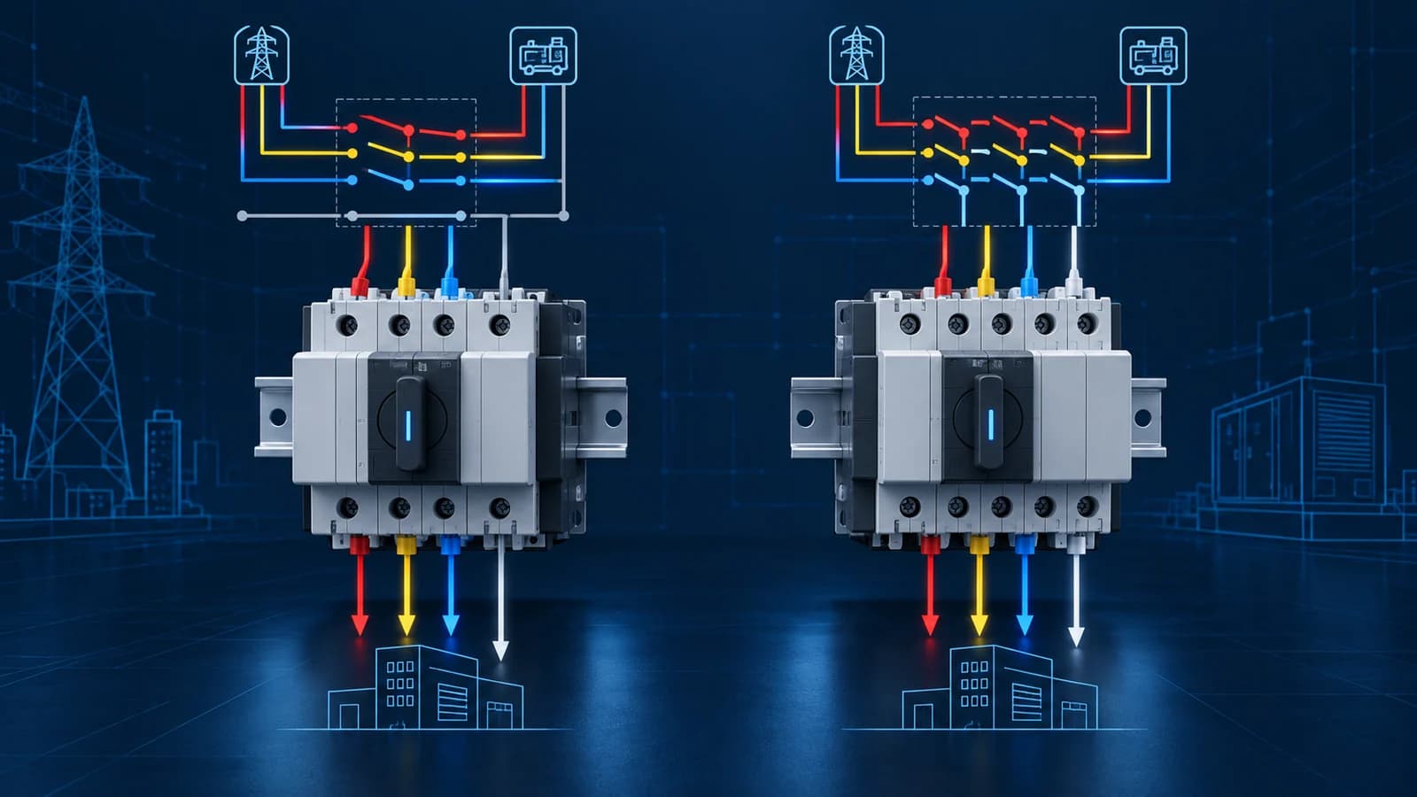
Short answer: a 3-pole automatic transfer switch changes the three phase conductors while the neutral normally remains solid. A 4-pole ATS changes all three phases and the neutral. The correct choice is determined by the system grounding and neutral arrangement—not simply by load current, price or a general preference for “more poles.” If the alternate source is treated as a separately derived system, a switched neutral is commonly required so that only the intended neutral-to-ground connection is active. The project engineer and applicable local rules must make the final decision.
That distinction looks simple on a catalog page, but it affects ground-fault current paths, nuisance tripping, equipment bonding and the way a generator-backed system is commissioned. It also explains why a supplier cannot responsibly recommend a 3P or 4P model from the current rating alone.
This guide gives panel builders, distributors, contractors and OEM buyers a practical way to discuss the decision. It does not replace the project one-line diagram, the generator bonding information, the authority having jurisdiction or a model-specific wiring manual.
What do “3-pole” and “4-pole” mean in a three-phase ATS?
In a three-phase automatic transfer switch, each switched pole opens and closes a current-carrying conductor as the load moves between Source A and Source B.
- A 3-pole ATS switches phases L1, L2 and L3. The neutral conductor normally remains continuously connected through a solid neutral bar or terminal arrangement.
- A 4-pole ATS switches L1, L2, L3 and neutral. Eaton describes the fourth pole in this application as a fully rated pole that performs like the individual phase poles.
“Solid neutral” does not mean that the neutral is unimportant. It means the neutral is not transferred by the switching mechanism. “Switched neutral” means the ATS deliberately connects the load neutral to the neutral of the selected source according to the product's transfer sequence.
The pole count must also match the actual system. In single-phase applications, the comparable decision may be 2P rather than 4P. A buyer should therefore state voltage, frequency, phase arrangement and neutral requirement instead of requesting “a 4-pole ATS” without context.
The deciding question: how is the alternate source grounded?
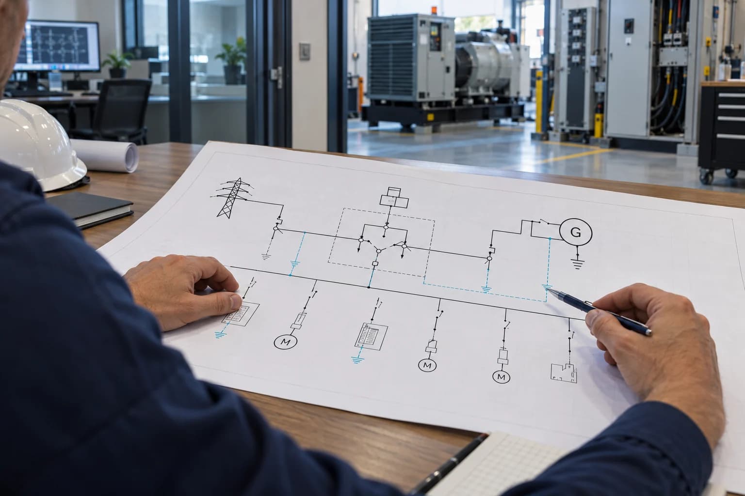
Schneider Electric's ASCO guidance states that selection between a solid and switched neutral depends on whether the distribution system is served by an alternate source that uses a separately derived ground. That is the core engineering question.
A generator can be configured so that its neutral is bonded to ground at the generator, or so that it relies on the normal system's neutral-ground connection. Those two arrangements do not create the same current path. If both sources have an active neutral-to-ground bond while their neutrals remain permanently connected, parallel paths can exist. If the system is intended to be separately derived, the ATS neutral pole is used to isolate the non-selected source neutral.
Do not infer this from the generator size or from the number of conductors visible in a photo. Review at least:
- the project one-line diagram;
- the normal-source grounding and bonding point;
- the generator or alternate-source neutral bonding method;
- the earth-fault or ground-fault protection scheme;
- the neutral conductor arrangement from both sources to the load;
- applicable electrical codes and the engineer's design basis.
When a customer writes only “400 V, 100 A, generator backup,” the pole decision is still open. A useful quotation should mark it for confirmation rather than silently choosing a model.
3-pole vs 4-pole ATS comparison
| Selection point | 3-pole ATS | 4-pole ATS |
|---|---|---|
| Switched conductors | Three phase conductors | Three phase conductors plus neutral |
| Neutral arrangement | Usually solid/continuous | Transferred with the selected source |
| Common design context | Alternate source is not treated as separately derived, subject to project design | Alternate source is treated as separately derived, subject to project design |
| Ground-fault coordination | Must be checked against shared-neutral current paths and protection | Must be checked against neutral-pole sequence and protection |
| Mechanical complexity | One fewer switched power pole | Additional fully rated pole and associated mechanism |
| Panel considerations | Often smaller, but dimensions are model-specific | May require more space; verify the exact drawing |
| Purchasing risk | Wrongly assuming a solid neutral is always acceptable | Wrongly assuming an extra pole automatically makes the design safer |
This table is a screening tool, not a code rule. A 4-pole switch is not an automatic upgrade, and a 3-pole switch is not automatically inadequate. The correct configuration is the one that implements the intended system design and has suitable model-specific ratings and documentation.
When is a 4-pole automatic transfer switch commonly considered?
When the generator is a separately derived source
If the generator neutral is bonded to ground at the generator and the design treats that supply as separately derived, the load neutral generally needs to transfer so the selected source provides the intended bonding point without maintaining an unwanted connection to the other source.
The exact requirement depends on the jurisdiction and system design. Procurement teams should avoid turning “separately derived” into a product label. It describes the electrical system, not merely the ATS.
When the ground-fault protection scheme requires neutral isolation
Ground-fault sensing can be affected by unintended neutral paths. A switched neutral may be part of the designed solution where source-specific ground-fault protection must operate correctly. The protection engineer should evaluate sensor location, bonding, conductor routing and the switch's neutral-pole behavior as one system.
When the project specification explicitly calls for a switched neutral
Tender documents may specify a 4-pole ATS, but buyers should still understand why. Confirm that the quotation, model suffix, datasheet, nameplate and wiring diagram all refer to the same 4P configuration. A generic brochure showing both 3P and 4P options is not proof that the offered model is correct.
When the installation must isolate source neutrals during transfer
Some projects require source-neutral isolation for operational or protection reasons. In that case, ask how the neutral pole is sequenced. Depending on the product design, the neutral may transfer simultaneously with the phase poles or use another defined sequence. Never assume all 4-pole products behave identically.
When can a 3-pole ATS be appropriate?
A 3-pole ATS can be appropriate when the system uses a solid neutral and the alternate source is not separately derived under the applicable design. The common neutral remains connected while the three phase conductors transfer.
This arrangement can be straightforward, but it still requires engineering review. Confirm that:
- the generator bonding arrangement matches the design;
- the common neutral path is correctly sized and terminated;
- the ground-fault protection scheme has been coordinated;
- both sources have compatible voltage and phase relationships for the intended transfer method;
- the ATS has the required utilization category and short-circuit capability;
- upstream protection is coordinated with the offered model.
The common mistake is to treat “3P” as only a cost or space choice. It is first a system choice.
Five mistakes that cause wrong ATS pole selection
1. Selecting from amperes alone
An ATS rated for the load current can still have the wrong pole arrangement, control voltage, transfer class or short-circuit coordination. Current is one input, not the complete specification.
2. Treating neutral and protective earth as interchangeable
Neutral and protective earth have different functions. Their connection is controlled at defined bonding points. Installation work must be performed by qualified personnel using the approved diagram and local requirements.
3. Assuming every generator has the same neutral bond
Portable, packaged and permanently installed generator systems may be supplied or configured differently. Obtain the manufacturer information and confirm the actual project arrangement.
4. Approving a generic wiring diagram
A family brochure may cover multiple currents, pole counts and control-voltage versions. Before panel production, freeze the exact model and obtain its terminal and wiring information.
5. Discovering the neutral decision after the panel layout is complete
Changing from 3P to 4P can affect device width, terminal space, cable routing, bill of materials and enclosure layout. Resolve it during electrical design, not during shipment inspection.
A practical pre-RFQ checklist
Send the following information when requesting a recommendation:
| Information | Example | Why the supplier needs it |
|---|---|---|
| Normal source | Utility | Defines Source A |
| Alternate source | Diesel generator | Identifies source behavior and control needs |
| System voltage/frequency | 400/230 V, 50 Hz | Confirms electrical compatibility |
| Phase arrangement | Three-phase, four-wire | Establishes conductor arrangement |
| Design current and load type | 80 A mixed commercial load | Supports preliminary rating review |
| Neutral-ground bond | Generator bonded neutral / unknown | Drives the switched-neutral discussion |
| Pole requirement | 3P, 4P or engineer to confirm | Prevents an unsupported assumption |
| Prospective fault current | Value at ATS location if available | Supports short-circuit coordination |
| Upstream protection | Breaker/fuse type and rating | Supports PC/CB architecture review |
| Transition method | Open transition unless otherwise specified | Defines source-transfer behavior |
| Control voltage | 110 V or 220 V where relevant | Prevents controller mismatch |
| Panel space | Available W × H × D | Supports mechanical fit |
| Destination market | Country/region | Frames code and document review |
If neutral bonding is not yet confirmed, say so. “Unknown—please mark for engineer review” is safer than an invented answer.
Factory testing, sample review and shipment inspection
Factory testing does not determine whether the engineering design should be 3P or 4P; that decision must already be defined. Testing and inspection verify that the supplied device matches the approved configuration and functions as specified.
During sample approval
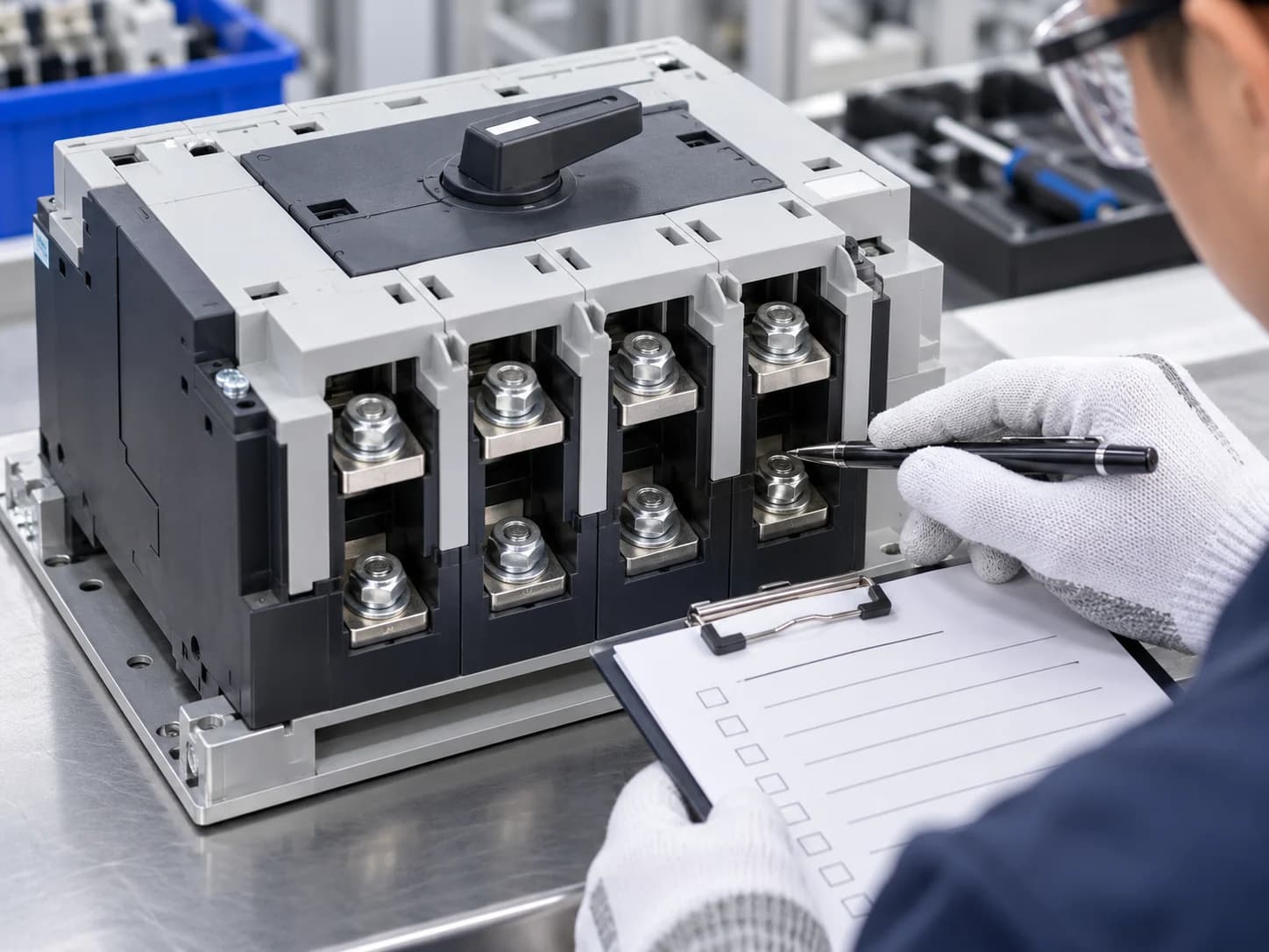
Check the complete model designation, rated current, voltage, frequency, pole count, control voltage and nameplate against the approved specification. Inspect terminal identification and request the matching wiring document. With all sources safely isolated and only under the manufacturer's instructions, qualified personnel can review manual operation and mechanical freedom.
During functional verification
A model-specific procedure may include source-sensing checks, transfer and retransfer operation, position indication, manual/automatic mode, generator-start contact and configured time delays. Schneider/ASCO's Series 185 procedure, for example, separates manual operation, voltage checks and electrical operation. It also warns that manual operation must not be attempted until both sources are disconnected. Use the procedure for the actual model; do not copy test times from another product.
During shipment inspection

Verify quantity, model suffix, pole count, accessories, labels, packaging condition and document version. Photograph the nameplate and terminal side of the approved sample and bulk units. For OEM orders, compare the private label with the frozen technical specification—branding must never obscure or contradict required ratings and safety information.
Installation preparation for a 3P or 4P ATS
Before energization, the installation team should review the manufacturer's instructions and the approved project drawings. Common preparation items include:
- isolate and verify both sources according to the site's safe-work procedure;
- check for shipping damage, loose parts or construction debris;
- confirm Source A, Source B and load connections;
- verify phase rotation and conductor identification;
- apply the manufacturer-specified terminal torque;
- confirm neutral and protective-earth connections exactly as designed;
- check controller settings, control wiring and generator-start contacts;
- reinstall all barriers and covers;
- perform the specified commissioning sequence with qualified personnel.
ABB's final-equipment inspection guidance similarly calls for checking cable connections, matching phase rotation, engine-start and control wiring, timer settings, lug torque, barriers and project documents before energization.
How LSP product families map to the pole discussion
LSP's current site data presents different pole choices by family:
- L2S Series: 2P, 3P and 4P options across a stated 10A-125A family, suited to compact DIN-rail applications.
- L2H Series: representative 2P and 4P options at 40A/63A with 110 V and 220 V control versions.
- M2R Series: representative 2P, 3P and 4P options at 40A, 63A and 100A.
These ranges allow a useful shortlist, but the final model must follow the project requirements. Confirm current, voltage, poles, control voltage, panel space, protection architecture and model-specific documents before ordering.
FAQ
Is a 4-pole ATS always better than a 3-pole ATS?
No. A 4-pole ATS switches the neutral; a 3-pole ATS normally keeps a solid neutral. The better choice is the one required by the grounding, bonding and protection design. An unnecessary or wrongly applied fourth pole is not an engineering improvement.
Does a generator always require a 4-pole transfer switch?
No. The decision depends on whether the generator is treated as a separately derived source and how its neutral is bonded. Review the generator documentation, one-line diagram and local requirements.
What is a switched-neutral ATS?
It is a transfer switch with a dedicated pole that transfers the load neutral between source neutrals. In a three-phase system this is commonly described as a 4-pole ATS.
Can I change from 3P to 4P after ordering?
Do not assume so. The mechanism, enclosure, terminals and model code may differ. Resolve the neutral decision before sample approval and panel production.
What should I send to an ATS supplier for pole selection?
Send the one-line diagram, normal and alternate source types, voltage, frequency, phase/wire arrangement, design current, neutral-ground bonding details, fault current, upstream protection, control voltage, panel space and destination market.
Can an ATS supplier make the final grounding decision?
The supplier can explain product options and identify missing information, but the responsible project engineer and applicable authority must approve the installation's grounding and bonding design.
Conclusion
The difference between a 3-pole and 4-pole automatic transfer switch is not simply one extra terminal. It is the decision to keep the neutral solid or to transfer it with the selected source. That decision interacts with the source grounding method, neutral-to-ground bonding, ground-fault protection and commissioning plan.
Start with the system drawing. Confirm how each source is grounded. Then select a product whose current, pole configuration, control voltage, transfer class, short-circuit capability and documentation match the project. This sequence reduces quotation revisions, panel redesign and site surprises.
Final CTA: Send Your Requirements
Preparing an ATS quotation or panel design? Send LSP your one-line diagram, voltage, current, source types, phase arrangement, neutral/grounding information, control voltage, available panel space and destination market. We will help organize a model shortlist and the documents that still need confirmation.
Technical references
- Eaton, “Automatic transfer switches fundamentals”: https://www.eaton.com/us/en-us/products/low-voltage-power-distribution-control-systems/automatic-transfer-switches/automatic-transfer-switch-fundamentals.html
- Schneider Electric / ASCO, “Neutral Configurations in Transfer Switches”: https://www.se.com/us/en/download/document/ASC-DB-NCTS/
- Schneider Electric / ASCO, “How to do a Functional Test after installing the Series 185 automatic transfer switch?”: https://www.se.com/uk/en/faqs/FAQ000234149/
- ABB Zenith transfer switch manual, final equipment inspection: https://library.e.abb.com/public/e224e9c5296d463d9813a115ae2409f4/1SCC301107M0201_Rev3.pdf
Editorial note: AI-generated visuals on this page are technical illustrations, not documentary evidence of a specific LSP factory, customer project, certificate or test result. Final product selection and installation require current model documents and qualified project review.